Gå til hovedinnhold
Havforskningsinstituttet
HI
English
<- Tilbake
Søk
Søk
Søk
View page in English
Figur
Fra rapporten:
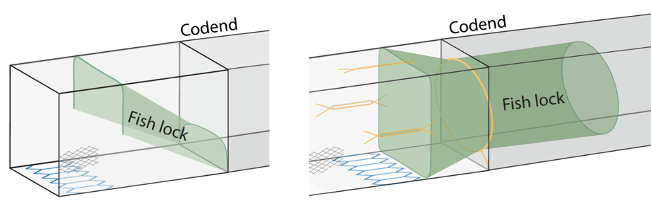
Catch Control in the Blue Whiting Pelagic Trawl Fishery
Figure 4.1 – Schematic diagrams of fish lock designs: Left – type 1, panel; Right – type 2, cylinder.